 ZOOMRY

1. Product Overview
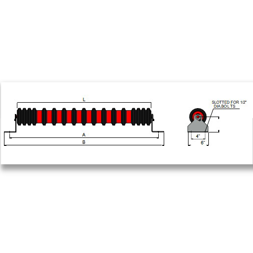
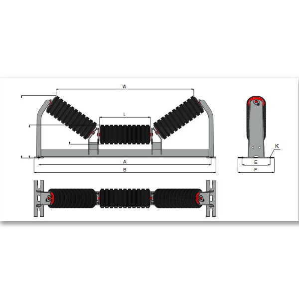
ZOOMRY CEMA D equal impact troughing idlers combine a symmetrical three equal-length roller design with molded rubber cushion rings for heavy-duty loading zone protection. Built to CEMA D standards for mining conveyors up to 72-inch belt width, these impact troughing idlers absorb up to 80% of impact energy at crusher discharge and transfer points — protecting both belt and structure from premature failure.
Unlike standard carrying idlers, each roller is fitted with rubber cushion rings spaced along the roller shell. These rings compress under falling material impact, then rebound — dissipating kinetic energy that would otherwise damage the belt carcass. Available in 20°, 35°, and 45° trough angles with 5-inch and 6-inch impact-rated rollers, labyrinth seals, and 50,000+ hour service life.
2. How Rubber Cushion Rings Work
At conveyor loading zones, material falling from a crusher or preceding conveyor generates high-energy impact forces concentrated at the point of belt contact. Standard carrying idlers transmit these forces directly to the belt carcass, accelerating splice fatigue and cover wear.
CEMA D equal impact troughing idlers solve this problem through molded rubber cushion rings installed at regular intervals along each of the three equal-length rollers. As material impacts the belt, these rings compress by up to 15mm — converting kinetic energy into elastic deformation. The rings then rebound slowly, preventing secondary shock waves through the belt. This mechanism absorbs up to 80% of impact energy, extending belt life by 2–3× at transfer points in cement and aggregate operations.
3. Key Features
Symmetrical Three Equal-Length Rollers — Uniform weight distribution across the full belt width, matching the CEMA D equal troughing geometry for consistent belt support from standard sections into loading zones.
Molded Rubber Cushion Rings — Multi-stage compression absorbs up to 80% of falling material impact energy, preventing belt puncture and splice damage at transfer points.
CEMA D Heavy-Duty Rating — 5-inch and 6-inch diameter impact-rated rollers with reinforced frames for belt widths up to 72 inches in aggregate quarry crusher discharge applications.
Three Trough Angles — Available in 20°, 35°, and 45° to match existing carrying idler geometry, ensuring seamless belt transition from standard sections into impact zones.
Advanced Labyrinth Sealing — Multi-stage seals protect bearings from fine dust and moisture ingress common in coal and mineral crushing environments.
4. Equal Impact vs Standard Equal Troughing
| Feature | CEMA D Equal Impact Troughing (D10) | CEMA D Equal Troughing (D9) |
|---|---|---|
| Roller Surface | Rubber cushion rings on steel shell | Smooth steel shell |
| Primary Function | Impact absorption + belt protection | Maximum carrying capacity |
| Impact Energy Absorption | Up to 80% | Minimal (steel-on-belt contact) |
| Best Application | Crusher discharge, transfer points, loading zones | Standard conveyor carrying sections |
| Spacing Recommendation | 300–450 mm at impact zone | 900–1,200 mm standard spacing |
5. Application Scenarios
Crusher Discharge Zones — Primary and secondary crusher outputs in mining operations where lump sizes up to 300 mm drop onto the receiving conveyor. Equal impact idlers are spaced at 300–450 mm centers to provide continuous belt support through the impact zone.
Transfer Points — Conveyor-to-conveyor transfer chutes in cement and aggregate plants where material free-fall height exceeds 2 meters. The rubber cushion rings prevent belt cover gouging and carcass fatigue.
Overland Conveyor Loading Sections — Long-distance overland conveyors transporting coal or minerals where the loading zone is the single highest-wear point. Equal impact idlers extend belt life by 2–3× at these critical locations.
6. Dimensions – CEMA D Equal Impact Troughing 20° / 35° / 45°
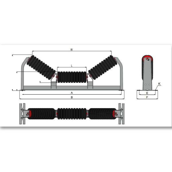
ZOOMRY CEMA D equal impact troughing idlers share the same frame geometry as CEMA D equal troughing idlers, with rubber cushion rings on each roller. Available in 5-inch and 6-inch impact-rated roller configurations for belt widths from 24 to 72 inches at all three standard trough angles:
|
|
5" Roller | 6" Roller |
|
||||||||||
|---|---|---|---|---|---|---|---|---|---|---|---|---|---|
| Angle | BW | A | B | L | H1 | H2 | W | H1 | H2 | W | E | F | K |
| 20° | 24 | 33 | 35 | 9 1/16 | 8 1/2 | 11 11/16 | 27 5/8 | 9 | 12 1/8 | 27 5/16 | 6 | 9 1/2 | 1/2 |
| 30 | 39 | 41 | 11 1/8 | 8 5/8 | 12 9/16 | 33 3/8 | 9 1/8 | 13 1/16 | 32 15/16 | 6 | 9 1/2 | 1/2 | |
| 36 | 45 | 47 | 13 1/4 | 8 5/8 | 13 5/16 | 39 7/16 | 9 1/8 | 13 3/4 | 39 1/8 | 6 | 9 1/2 | 1/2 | |
| 42 | 51 | 53 | 15 7/16 | 9 | 14 7/16 | 45 3/4 | 9 1/2 | 14 7/8 | 45 7/16 | 7 1/2 | 9 1/2 | 5/8 | |
| 48 | 57 | 59 | 17 1/16 | 9 | 14 7/8 | 50 5/8 | 9 1/2 | 15 3/8 | 50 5/16 | 7 1/2 | 9 1/2 | 5/8 | |
| 54 | 63 | 65 | 19 1/16 | 9 | 15 3/4 | 56 7/16 | 9 1/2 | 16 1/8 | 56 1/16 | 9 | 11 | 5/8 | |
| 60 | 69 | 71 1/2 | 21 1/16 | 9 | 16 1/2 | 62 3/16 | 9 1/2 | 16 3/4 | 61 7/8 | 9 | 11 | 5/8 | |
| 72 | 81 | 83 1/2 | 26 | 9 1/2 | 18 3/8 | 76 3/16 | 10 | 18 7/8 | 75 13/16 | 9 | 11 | 5/8 | |
| 35° | 24 | 33 | 35 | 9 1/16 | 8 1/2 | 13 13/16 | 24 11/16 | 9 | 14 3/16 | 24 1/8 | 6 | 9 1/2 | 1/2 |
| 30 | 39 | 41 | 11 1/8 | 8 5/8 | 15 3/16 | 30 3/8 | 9 1/8 | 15 11/16 | 29 13/16 | 6 | 9 1/2 | 1/2 | |
| 36 | 45 | 47 | 13 1/4 | 8 5/8 | 16 3/8 | 35 15/16 | 9 1/8 | 16 13/16 | 35 7/16 | 6 | 9 1/2 | 1/2 | |
| 42 | 51 | 53 | 15 7/16 | 9 | 18 1/16 | 41 3/4 | 9 1/2 | 18 7/16 | 41 3/16 | 7 1/2 | 9 1/2 | 5/8 | |
| 48 | 57 | 59 | 17 1/16 | 9 | 18 7/8 | 45 13/16 | 9 1/2 | 19 1/4 | 45 1/4 | 7 1/2 | 9 1/2 | 5/8 | |
| 54 | 63 | 65 | 19 1/16 | 9 | 20 | 51 1/8 | 9 1/2 | 20 7/16 | 50 1/2 | 9 | 11 | 5/8 | |
| 60 | 69 | 71 1/2 | 21 1/16 | 9 | 21 3/16 | 56 3/8 | 9 1/2 | 21 9/16 | 55 13/16 | 9 | 11 | 5/8 | |
| 72 | 81 | 83 1/2 | 26 | 9 1/2 | 24 7/16 | 69 9/16 | 10 | 24 7/8 | 69 1/16 | 9 | 11 | 5/8 | |
| 45° | 24 | 33 | 35 | 9 1/16 | 8 1/2 | 15 1/16 | 22 3/4 | 9 | 15 7/16 | 22 1/16 | 6 | 9 1/2 | 1/2 |
| 30 | 39 | 41 | 11 1/8 | 8 5/8 | 16 3/4 | 28 1/16 | 9 1/8 | 17 1/16 | 27 3/8 | 6 | 9 1/2 | 1/2 | |
| 36 | 45 | 47 | 13 1/4 | 8 5/8 | 18 3/16 | 33 1/8 | 9 1/8 | 18 9/16 | 32 5/16 | 6 | 9 1/2 | 1/2 | |
| 42 | 51 | 53 | 15 7/16 | 9 | 20 1/8 | 38 7/16 | 9 1/2 | 20 1/2 | 37 11/16 | 7 1/2 | 9 1/2 | 5/8 | |
| 48 | 57 | 59 | 17 1/16 | 9 | 21 3/16 | 42 1/16 | 9 1/2 | 21 9/16 | 41 3/8 | 7 1/2 | 9 1/2 | 5/8 | |
| 54 | 63 | 65 | 19 1/16 | 9 | 22 7/8 | 46 15/16 | 9 1/2 | 23 | 46 3/16 | 9 | 11 | 5/8 | |
| 60 | 69 | 71 1/2 | 21 1/16 | 9 | 24 1/16 | 51 3/4 | 9 1/2 | 24 3/8 | 51 | 9 | 11 | 5/8 | |
| 72 | 81 | 83 1/2 | 26 | 9 1/2 | 28 | 63 15/16 | 10 | 28 5/16 | 63 1/4 | 9 | 11 | 5/8 | |
Related Solutions

How to Select Impact Idlers for Your Loading Zone?
Tell us your material lump size, drop height, and belt width — our engineers will recommend the optimal impact idler configuration with correct cushion ring spacing.
Impact Idler Selection Guide →