 ZOOMRY

1. Product Overview
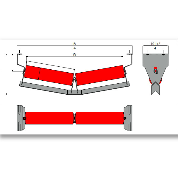
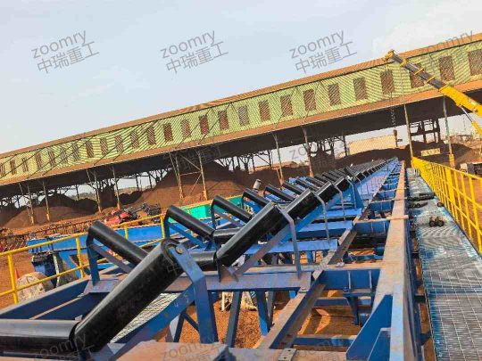
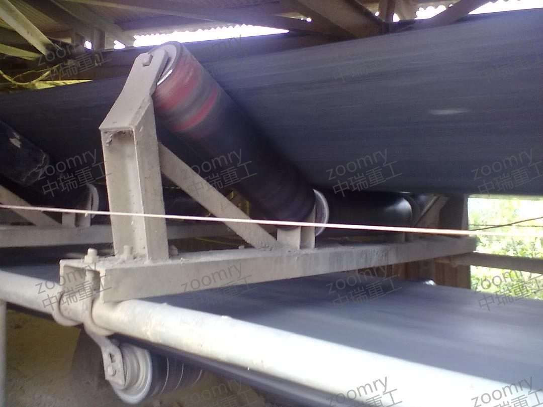
ZOOMRY CEMA B unequal impact troughing idlers combine an offset L1/L2 roller geometry with rubber cushion rings for light-duty loading zone belt support. Designed for selected CEMA B conveyor applications up to 48-inch belt width, these impact troughing idlers use a longer center roller (L1) with shorter wing rollers (L2) to provide a project-specific carrying-side support arrangement at transfer and loading zones. Available in 20° and 35° trough angles with 4-inch and 5-inch impact-rated rollers and labyrinth sealing options.
Unlike an equal impact idler with three equal-length rollers, the unequal configuration uses different center and wing roller lengths to suit selected belt profiles, frame arrangements, loading conditions, or retrofit dimensions. Rubber cushion rings on the rollers compress under falling material and help reduce localized impact on the belt at suitable light-duty loading zones in aggregate, coal, cement, and mineral processing applications.
2. How Unequal Impact Roller Geometry Works
At conveyor loading zones, the center of the belt carries the heaviest material burden and receives the highest impact force from falling material. An equal-length roller design distributes support uniformly — but in certain frame arrangements, retrofit situations, or specific loading patterns, an offset L1/L2 configuration may be required to match existing conveyor geometry.
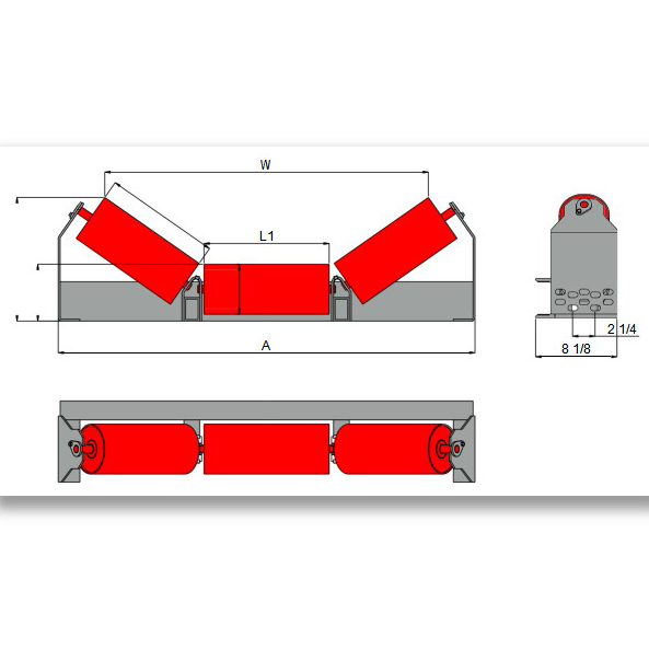
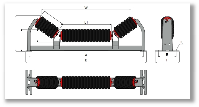
The CEMA B unequal impact troughing idler uses a longer center roller (L1) with shorter wing rollers (L2). This support arrangement is selected for specific frame geometry and loading conditions — not as a belt tracking correction device. The rubber cushion rings on each roller compress under falling material, helping reduce localized belt contact stress at suitable loading zones in mining and quarry conveyor applications.
3. Key Features
Offset L1/L2 Roller Geometry — Longer center roller (L1) with shorter wing rollers (L2) provides a support arrangement selected for specific frame geometry, loading conditions, or retrofit dimensions.
Rubber Cushion Rings — Rubber rings on the rollers provide cushioning at suitable loading zones, helping reduce localized material impact and belt contact stress compared with standard steel carrying rollers.
CEMA B Light-Duty Rating — 4-inch and 5-inch impact-rated rollers for belt widths up to 48 inches — suitable for light-duty crusher discharge in aggregate and sand processing operations.
Two Trough Angles — Available in 20° and 35° to match standard CEMA B carrying idler geometry, ensuring compatible belt transition into loading zones.
Advanced Labyrinth Sealing — Multi-stage seals protect bearings from fine dust and moisture, delivering extended service life under normal operating conditions.
4. Unequal Impact vs Equal Impact Troughing (CEMA B)
| Feature | CEMA B Unequal Impact (B10) | CEMA B Equal Impact (B8) |
|---|---|---|
| Roller Configuration | L1 (long center) + L2 (short wings) | 3 equal-length rollers |
| Support Geometry | Offset L1/L2 roller lengths for selected loading-zone and frame requirements | Symmetrical three equal-length roller arrangement |
| Trough Angles | 20° and 35° | 20°, 35°, and 45° |
| Best For | Frame-specific layouts, retrofit dimensions, non-standard loading arrangements | Standard centered loading arrangements |
5. Dimensions – CEMA B Unequal Impact Troughing 20° / 35°
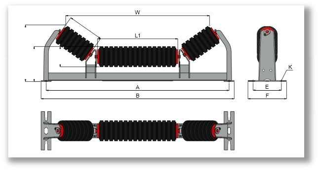
ZOOMRY CEMA B unequal impact troughing idlers are manufactured with 4-inch and 5-inch impact-rated roller configurations for belt widths from 18 to 48 inches at 20° and 35° trough angles. Suitable for light-duty CEMA B loading zones in mining, coal, cement, and aggregate conveyors:
|
|
4" Roller | 5" Roller |
|
|||||||||||
|---|---|---|---|---|---|---|---|---|---|---|---|---|---|---|
| Angle | BW | A | B | L1 | L2 | H1 | H2 | W | H1 | H2 | W | E | F | K |
| 20° | 18 | 27 | 29 | 11 1/2 | 4 1/2 | 6 1/2 | 8 5/8 | 21 1/4 | 7 | 9 1/16 | 20 7/8 | 6 | 8 | 1/2 |
| 24 | 33 | 35 | 15 7/16 | 5 7/16 | 6 1/2 | 8 5/8 | 27 1/4 | 7 | 9 1/16 | 26 15/16 | 6 | 8 | 1/2 | |
| 30 | 39 | 41 | 21 3/8 | 5 7/16 | 6 1/2 | 8 5/8 | 33 1/8 | 7 | 9 1/16 | 32 7/8 | 6 | 8 | 1/2 | |
| 36 | 45 | 47 | 27 3/8 | 5 7/16 | 6 1/2 | 8 5/8 | 39 1/8 | 7 | 9 1/16 | 38 7/8 | 6 | 8 | 1/2 | |
| 42 | 51 | 53 | 33 3/8 | 5 7/16 | 7 | 9 1/16 | 45 1/8 | 7 1/2 | 9 9/16 | 44 7/8 | 7 1/2 | 9 1/2 | 5/8 | |
| 48 | 57 | 59 | 39 3/8 | 5 7/16 | 7 | 9 1/16 | 51 1/8 | 7 1/2 | 9 9/16 | 50 7/8 | 7 1/2 | 9 1/2 | 5/8 | |
| 35° | 18 | 27 | 29 | 10 7/16 | 5 3/8 | 6 1/2 | 10 3/16 | 19 1/8 | 7 | 10 9/16 | 18 11/16 | 6 | 8 | 1/2 |
| 24 | 33 | 35 | 13 1/4 | 6 3/4 | 6 1/2 | 10 3/16 | 24 7/8 | 7 | 10 9/16 | 24 7/16 | 6 | 8 | 1/2 | |
| 30 | 39 | 41 | 15 7/16 | 8 15/16 | 6 1/2 | 11 1/2 | 30 3/4 | 7 | 11 7/8 | 30 3/16 | 6 | 8 | 1/2 | |
| 36 | 45 | 47 | 21 3/8 | 8 15/16 | 6 1/2 | 11 1/2 | 36 5/8 | 7 | 11 7/8 | 36 1/16 | 6 | 8 | 1/2 | |
| 42 | 51 | 53 | 21 3/8 | 11 1/8 | 7 | 13 1/4 | 40 3/4 | 7 1/2 | 13 5/8 | 40 3/16 | 7 1/2 | 9 1/2 | 5/8 | |
| 48 | 57 | 59 | 27 3/8 | 11 1/8 | 7 | 13 1/4 | 46 3/4 | 7 1/2 | 13 5/8 | 46 3/16 | 7 1/2 | 9 1/2 | 5/8 | |
Dimensions shown are based on the listed CEMA B configuration reference. Final roller diameter, roller length, frame geometry, rubber ring arrangement, mounting dimensions, and loading-zone suitability should be confirmed against the conveyor drawing and operating duty.
What Information Do We Need for Impact Idler Selection?
- Material type, maximum lump size, and drop height at the loading zone
- Belt width, belt speed, and conveyor capacity
- Frame geometry and existing idler dimensions — especially for retrofit applications
- Operating environment — dust, moisture, temperature range, and material abrasiveness
- Existing idler type, frame dimensions, and whether this is a retrofit or new installation
Related Loading Zone Solutions

Need Impact Idlers for Your Loading Zone?
Tell us your material lump size, drop height, and frame dimensions — our engineers will confirm whether unequal or equal impact idler geometry fits your loading-zone requirements.
Request Impact Idler Recommendation →