 ZOOMRY

1. Product Overview
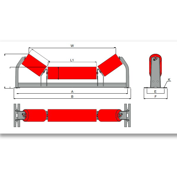
ZOOMRY CEMA B unequal troughing idlers feature an offset L1/L2 roller configuration for light-duty carrying side support on conveyors up to 36-inch belt width. Engineered to CEMA B standards for mining and industrial applications, these troughing idlers use a longer center roller (L1) with shorter wing rollers (L2) — providing better material containment and belt tracking compared with equal-length designs. Available in 20° and 35° trough angles with 4-inch and 5-inch diameter rollers and labyrinth seals.
CEMA B is the light-duty classification for small to medium conveyors handling materials such as sand, gravel, grain, and packaged goods. Unequal troughing idlers are particularly effective in aggregate and light industrial applications where the offset roller geometry helps prevent belt edge spillage and mistracking on narrower conveyors.
2. Unequal vs Equal Troughing: How L1/L2 Geometry Works
In a standard equal troughing idler, all three rollers share the same length — distributing material weight symmetrically across the belt. This works well for centered, uniform loading. But on narrower light-duty conveyors where feeding is often less controlled, the belt edges are more susceptible to spillage and drift.
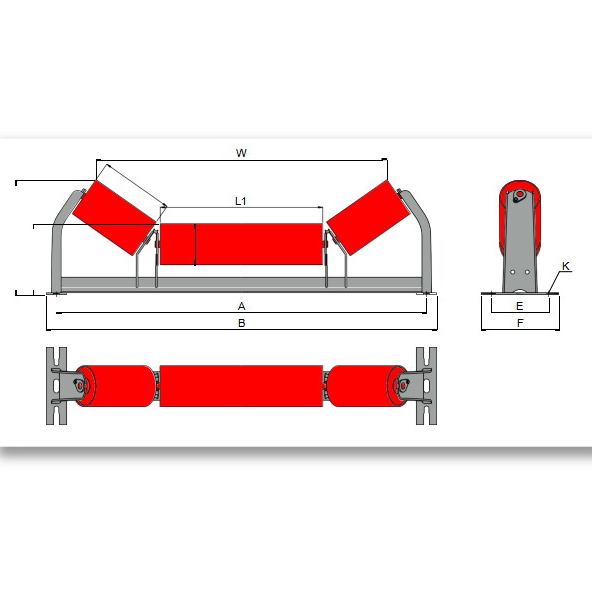
The CEMA B unequal troughing idler addresses this with an offset design: the center roller (L1) is longer, providing more support where the material burden is heaviest, while the shorter wing rollers (L2) create steeper outer angles that help contain material within the belt profile. This geometry is particularly beneficial on cement and aggregate conveyors where irregular loading is common.
3. Key Features
Offset L1/L2 Roller Geometry — Longer center roller with shorter wing rollers improves material containment and belt tracking on light-duty conveyors compared with equal-length designs in aggregate and sand handling applications.
CEMA B Light-Duty Rating — 4-inch and 5-inch diameter rollers engineered for belt widths up to 36 inches — the standard carrying side specification for small to medium industrial conveyors.
Two Trough Angles — Available in 20° and 35° to match material characteristics and throughput requirements for light-duty conveying.
IP66 Labyrinth Sealing — Multi-stage labyrinth plus contact seals protect bearings from dust and moisture in coal and bulk material handling environments.
Corrosion Resistance Options — Hot-dip galvanizing, painting, or stainless steel construction available for corrosive and washdown environments.
4. Unequal Troughing vs Equal Troughing (CEMA B)
| Feature | CEMA B Unequal Troughing (B1) | CEMA B Equal Troughing (B7) |
|---|---|---|
| Roller Configuration | L1 (long center) + L2 (short wings) | 3 equal-length rollers |
| Material Containment | Better — steeper wing angles reduce spillage | Standard — uniform trough profile |
| Belt Tracking | Improved — offset geometry aids centering | Baseline — frame alignment dependent |
| Trough Angles | 20° and 35° | 20°, 35°, and 45° |
| Best For | Irregular loading, spillage-prone narrow conveyors | Centered loading, maximum capacity |
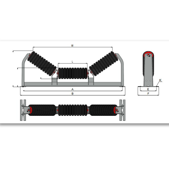
5. Dimensions – CEMA B Unequal Troughing 20° / 35°
ZOOMRY CEMA B unequal troughing idlers are manufactured with 4-inch and 5-inch roller configurations for belt widths from 18 to 36 inches. Suitable for light-duty CEMA B carrying sections in mining, aggregate, cement, and industrial conveyors:
|
|
4" Roller | 5" Roller |
|
|||||||||||
|---|---|---|---|---|---|---|---|---|---|---|---|---|---|---|
| Angle | BW | A | B | L1 | L2 | H1 | H2 | W | H1 | H2 | W | E | F | K |
| 20° | 18 | 27 | 29 | 11 1/2 | 4 1/2 | 6 1/2 | 8 5/8 | 21 1/4 | 7 | 9 1/16 | 20 7/8 | 6 | 8 | 1/2 |
| 24 | 33 | 35 | 15 7/16 | 5 7/16 | 6 1/2 | 8 5/8 | 27 1/4 | 7 | 9 1/16 | 26 15/16 | 6 | 8 | 1/2 | |
| 30 | 39 | 41 | 21 3/8 | 5 7/16 | 6 1/2 | 8 5/8 | 33 1/8 | 7 | 9 1/16 | 32 7/8 | 6 | 8 | 1/2 | |
| 36 | 45 | 47 | 27 3/8 | 5 7/16 | 6 1/2 | 8 5/8 | 39 1/8 | 7 | 9 1/16 | 38 7/8 | 6 | 8 | 1/2 | |
| 35° | 18 | 27 | 29 | 10 7/16 | 5 3/8 | 6 1/2 | 10 3/16 | 19 1/8 | 7 | 10 9/16 | 18 11/16 | 6 | 8 | 1/2 |
| 24 | 33 | 35 | 13 1/4 | 6 3/4 | 6 1/2 | 10 3/16 | 24 7/8 | 7 | 10 9/16 | 24 7/16 | 6 | 8 | 1/2 | |
| 30 | 39 | 41 | 15 7/16 | 8 15/16 | 6 1/2 | 11 1/2 | 30 3/4 | 7 | 11 7/8 | 30 3/16 | 6 | 8 | 1/2 | |
| 36 | 45 | 47 | 21 3/8 | 8 15/16 | 6 1/2 | 11 1/2 | 36 5/8 | 7 | 11 7/8 | 36 1/16 | 6 | 8 | 1/2 | |
Dimensions per CEMA B industry standards. A=Frame width, B=Overall width, L1=Center roller length, L2=Wing roller length, H1=Base height, H2=Overall height, W=Center-to-center mounting width, E/F/K=Mounting dimensions. All dimensions in inches. For custom belt widths or metric equivalents, contact ZOOMRY.
What Information Do We Need for Troughing Idler Selection?
- Belt width, conveyor capacity, and material characteristics
- Trough angle requirement and idler spacing
- Material type, bulk density, and maximum lump size
- Operating environment — dust, moisture, temperature range, and corrosion risks
- Existing idler type, frame dimensions, and whether this is a retrofit or new installation
Related Solutions

Need Unequal Troughing Idlers for Your Light-Duty Conveyor?
Tell us your belt width, material type, and trough angle — our engineers will recommend the optimal L1/L2 configuration for your carrying side.
Request Troughing Idler Recommendation →