 ZOOMRY

1. Product Overview
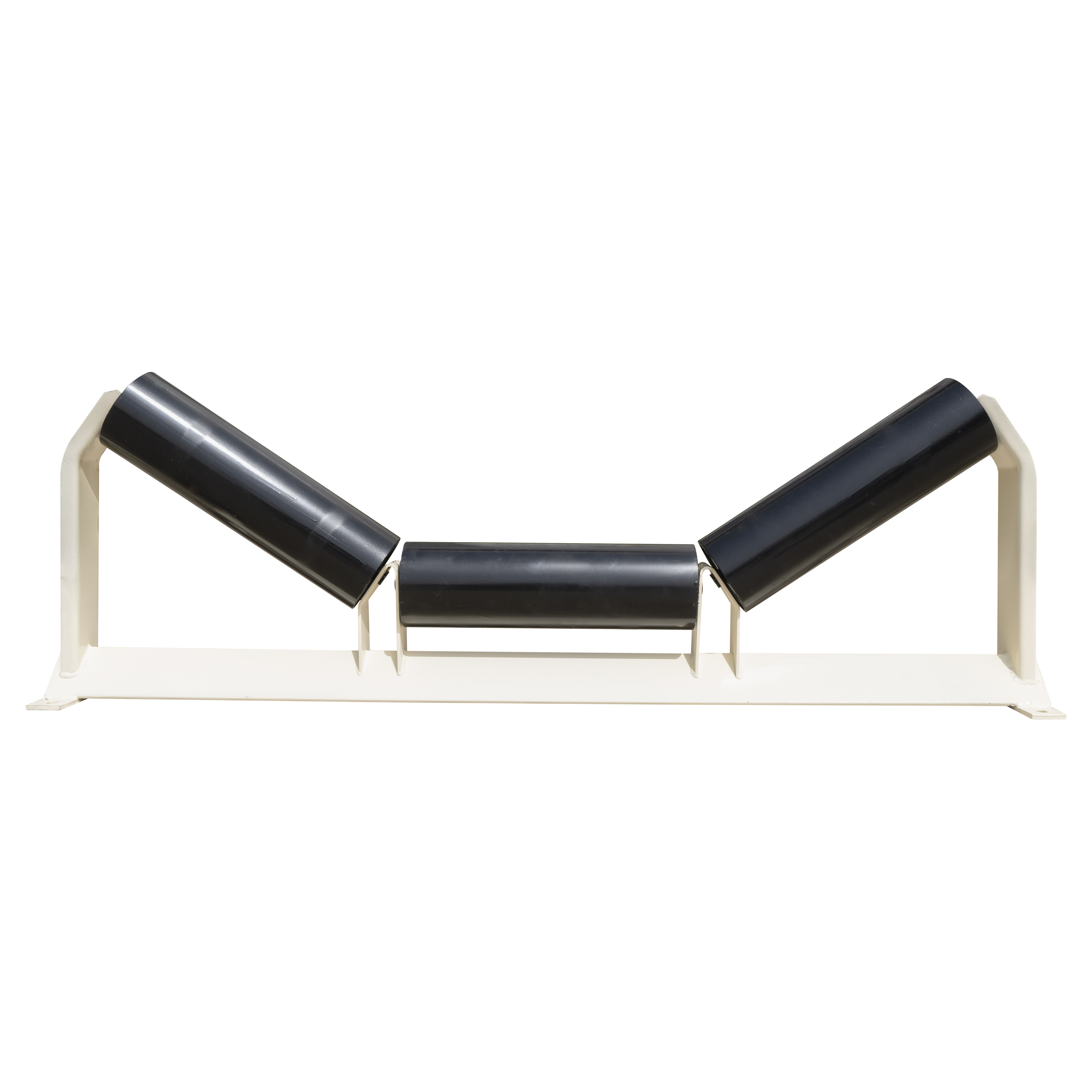
ZOOMRY CEMA D unequal impact troughing idlers are heavy-duty loading zone components with offset roller design and reinforced impact absorption. Built to CEMA D standards for mining crusher discharge and transfer points, these impact idlers combine L1 longer center and L2 shorter wing rollers with rubber cushion rings — absorbing up to 80% of falling material energy at loading zones.
Compared to CEMA E unequal impact idlers for extra heavy-duty 96-inch belts, the CEMA D version covers the heavy-duty 24–72 inch range — the most common belt width class for aggregate crushing circuits, coal transfer points, and cement plant conveyor loading zones.
2. Why Impact Idlers for Heavy-Duty Loading Zones?
Loading zones are the most vulnerable points on any heavy-duty conveyor. Falling material — whether run-of-mine ore from a crusher or aggregate from a truck dump hopper — strikes the Conveyor Belt with concentrated force. Standard troughing idlers cannot absorb this impact, leading to belt cover damage, carcass fatigue, and premature bearing failure.
CEMA D unequal impact troughing idlers address this with rubber cushion rings on all three rollers. These rings dissipate up to 80% of falling material energy, distributing impact forces across the idler frame rather than concentrating them on belt contact points. The unequal roller design further enhances protection — the longer center roller (L1) provides extended support surface directly under the material drop zone, reducing belt puncture incidents by over 60% compared to standard troughing idlers at transfer points.
3. Key Features
CEMA D Heavy-Duty Impact Rating — Engineered specifically for loading zones with 5" and 6" diameter impact rollers, rubber cushion rings, and reinforced frames for belt widths up to 72 inches.
Unequal Offset Design — Longer center roller (L1) + shorter wing rollers (L2) provide enhanced support directly under the impact zone where material drops, improving belt tracking on the carrying side.
Rubber Cushion Rings — Impact-absorbing rubber rings on all three rollers dissipate up to 80% of impact energy, reducing belt stress in aggregate quarry and mining crusher discharge applications.
Advanced Labyrinth Sealing — Multi-stage seals protect bearings from fine dust generated at transfer points, maintaining rotational resistance ≤2N.
Dual Trough Angles — Available in 20° and 35° angles to match material characteristics and loading zone conveyor design.
4. Application Scenarios
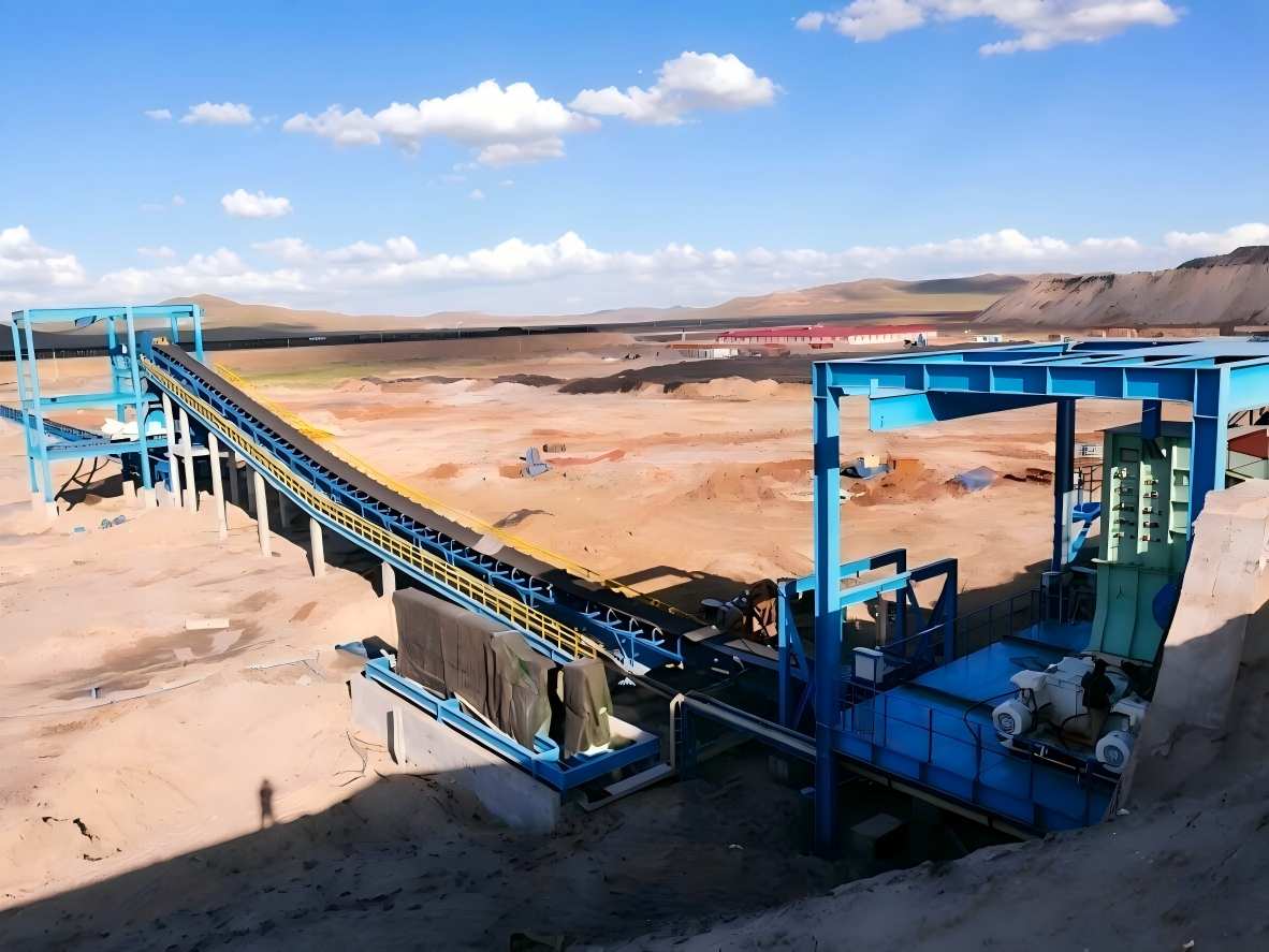
Primary Crusher Discharge — Run-of-mine ore dropping onto takeaway conveyors in mining operations. CEMA D impact idlers with unequal roller design provide maximum belt protection at the most critical loading point.
Aggregate Transfer Points — Conveyor-to-conveyor transfer chutes in aggregate quarry crushing circuits where material free-falls onto receiving belts.
Cement Plant Loading — Limestone and clinker transfer points in cement plants where abrasive materials require impact-rated idlers for continuous 24/7 operation.
5. Dimensions – CEMA D Unequal Impact Troughing 20° / 35°
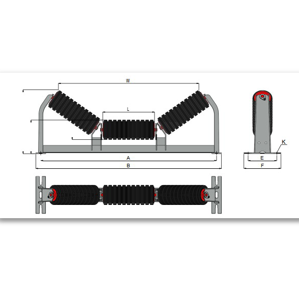
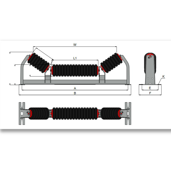
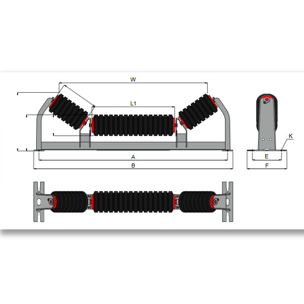
ZOOMRY CEMA D unequal impact troughing idlers are manufactured to CEMA D industry-standard dimensions with L1 (long center roller) and L2 (short wing rollers) offset configuration. Available in 5-inch and 6-inch roller diameters for belt widths from 24 to 72 inches:
|
|
5" Roller | 6" Roller |
|
||||||||||||
|---|---|---|---|---|---|---|---|---|---|---|---|---|---|---|---|
| Angle | BW | A | B | L1 | L2 | H1 | H2 | W | H1 | H2 | W | E | F | K | |
| 20° | 24 | 33 | 35 | 15 7/16 | 5 7/16 | 7 | 9 1/16 | 26 15/16 | 7 1/2 | 9 7/16 | 26 9/16 | 6 | 8 | 1/2 | |
| 30 | 39 | 41 | 21 3/8 | 5 7/16 | 7 | 9 1/16 | 32 7/8 | 7 1/2 | 9 7/16 | 32 1/2 | 6 | 8 | 1/2 | ||
| 36 | 45 | 47 | 27 3/8 | 5 7/16 | 7 | 9 1/16 | 38 7/8 | 7 1/2 | 9 7/16 | 38 1/2 | 6 | 8 | 1/2 | ||
| 42 | 51 | 53 | 33 3/8 | 5 7/16 | 7 1/2 | 9 9/16 | 44 7/8 | 8 | 9 15/16 | 44 1/2 | 7 1/2 | 9 1/2 | 5/8 | ||
| 48 | 57 | 59 | 39 3/8 | 5 7/16 | 7 1/2 | 9 9/16 | 50 7/8 | 8 | 9 15/16 | 50 1/2 | 7 1/2 | 9 1/2 | 5/8 | ||
| 54 | 63 | 65 | 45 3/8 | 5 7/16 | 9 | 11 | 56 7/8 | 9 1/2 | 11 7/16 | 56 9/16 | 9 | 11 | 5/8 | ||
| 60 | 69 | 71 1/2 | 51 3/8 | 5 7/16 | 9 | 11 | 62 7/8 | 9 1/2 | 11 7/16 | 62 9/16 | 9 | 11 | 5/8 | ||
| 72 | 81 | 83 1/2 | 63 3/8 | 5 7/16 | 9 1/2 | 11 3/8 | 74 7/8 | 10 | 11 13/16 | 74 9/16 | 9 | 11 | 5/8 | ||
| 35° | 24 | 33 | 35 | 13 1/4 | 6 3/4 | 7 | 11 | 25 7/16 | 7 1/2 | 11 3/8 | 24 7/8 | 6 | 8 | 1/2 | |
| 30 | 39 | 41 | 15 7/16 | 8 15/16 | 7 | 12 1/4 | 31 1/4 | 7 1/2 | 12 5/8 | 30 11/16 | 6 | 8 | 1/2 | ||
| 36 | 45 | 47 | 21 3/8 | 8 15/16 | 7 | 12 1/4 | 37 1/8 | 7 1/2 | 12 5/8 | 36 9/16 | 6 | 8 | 1/2 | ||
| 42 | 51 | 53 | 21 3/8 | 11 1/8 | 7 1/2 | 14 | 40 3/16 | 8 | 14 3/8 | 40 3/4 | 7 1/2 | 9 1/2 | 5/8 | ||
| 48 | 57 | 59 | 27 3/8 | 11 1/8 | 7 1/2 | 14 | 46 3/4 | 8 | 14 3/8 | 46 | 7 1/2 | 9 1/2 | 5/8 | ||
| 54 | 63 | 65 | 33 3/8 | 11 1/8 | 9 | 15 9/16 | 52 5/8 | 9 1/2 | 15 7/8 | 52 1/16 | 9 | 11 | 5/8 | ||
| 60 | 69 | 71 1/2 | 39 3/8 | 11 1/8 | 9 | 15 9/16 | 58 5/8 | 9 1/2 | 15 7/8 | 58 1/16 | 9 | 11 | 5/8 | ||
| 72 | 81 | 83 1/2 | 51 3/8 | 11 1/8 | 9 1/2 | 15 7/8 | 70 5/8 | 10 | 16 5/16 | 70 1/16 | 9 | 11 | 5/8 | ||
Related Solutions

How to Choose the Right CEMA D Impact Idler?
Tell us your material type, drop height, and belt width — our engineers will recommend the optimal impact idler configuration for your loading zone.
Impact Idler Selection Guide →