 ZOOMRY

1. Product Overview
ZOOMRY CEMA D self-aligning troughing idlers are heavy-duty carrying side components with automatic belt tracking correction via pivot-mounted frame and guide rollers. Built to CEMA D standards for mining and bulk material handling, these self-aligning idlers detect belt misalignment and steer the belt back to center — reducing edge wear by up to 50% on long overland and reversible conveyors without sensors or external power.
Compared to CEMA E self-aligning troughing idlers for extra heavy-duty 96-inch belts, the CEMA D version uses an L1/L2 offset roller configuration with 5-inch and 6-inch diameters — covering the heavy-duty 24–72 inch belt width range for standard mining and cement plant conveyors.
2. How Self-Aligning Troughing Idlers Work
CEMA D self-aligning troughing idlers operate on a fully mechanical principle — a pivot-mounted idler frame with side guide rollers detects lateral belt movement. When the loaded belt drifts to one side, it contacts the guide roller, applying force that pivots the entire frame. The angled L1/L2 offset rollers then redirect the belt back toward center. No sensors, no power source, no operator intervention required.
This continuous passive correction reduces belt edge damage by up to 50% compared to fixed troughing idlers. On long overland conveyors, self-aligning idlers are typically installed every 30–50 meters to maintain Conveyor Belt alignment across the entire length. The L1/L2 offset design provides additional tracking stability — the longer center roller naturally guides the belt while wing rollers create the trough profile.
3. Self-Aligning vs Fixed Troughing: Key Comparison
| Feature | CEMA D Self-Aligning | CEMA D Fixed Troughing |
|---|---|---|
| Belt Tracking | Automatic, real-time correction | Passive — no correction |
| Frame Type | Pivot-mounted with guide rollers | Fixed rigid frame |
| Edge Wear Reduction | Up to 50% | No reduction |
| Power Required | None — fully mechanical | None |
| Best For | Long overland, reversible, high-speed belts | Short conveyors with stable tracking |
4. Key Features
Automatic Belt Tracking — Pivot-mounted frame with side guide rollers continuously corrects belt misalignment without sensors or power — essential for unmanned conveyor stations in aggregate quarry operations.
CEMA D Heavy-Duty Rating — L1/L2 offset roller design with reinforced pivot bearings for 24–72 inch belt widths and 5-inch/6-inch diameter rollers.
Three Trough Angles — Available in 20°, 35°, and 45° to match material characteristics and conveyor design requirements.
Reversible Conveyor Compatible — Guide rollers function in both belt directions, making these idlers suitable for reversible conveyors in stacking and tripper applications.
Strategic Installation Spacing — Typically installed every 30–50 meters to maintain continuous belt alignment without over-correction.
5. Application Scenarios
Long Overland Conveyors — Mining conveyors spanning several kilometers in mining operations where belt drift accumulates over distance. Self-aligning idlers every 30-50 meters prevent progressive mistracking.
Reversible Conveyors — Stacker and tripper belts in port terminal stockyards where belt direction changes cause tracking instability in both directions.
High-Speed Carrying Belts — Conveyors above 4 m/s where small misalignments rapidly escalate into edge damage. Self-aligning idlers provide immediate correction.
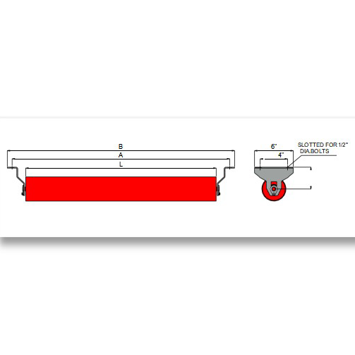
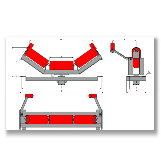
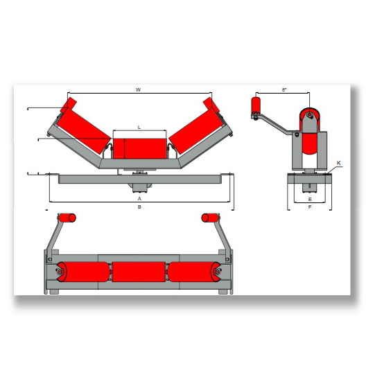
6. Dimensions – CEMA D Self-Aligning Troughing 20° / 35° / 45°
ZOOMRY CEMA D self-aligning troughing idlers use an L1/L2 offset roller configuration with pivot-mounted frame and guide rollers. Available in 5-inch and 6-inch diameters for belt widths from 24 to 72 inches:
|
|
5" Roller | 6" Roller |
|
||||||||||||
|---|---|---|---|---|---|---|---|---|---|---|---|---|---|---|---|
| Angle | BW | A | B | L1 | L2 | H1 | H2 | W | H1 | H2 | W | E | F | K | |
| 20° | 24 | 33 | 35 | 9 1/16 | 7 1/16 | 8 7/8 | 12 1/2 | 27 1/16 | 9 7/16 | 12 9/16 | 26 7/8 | 6 | 11 | 5/8 | |
| 30 | 39 | 41 | 15 7/16 | 7 1/16 | 8 7/8 | 12 1/2 | 33 1/16 | 9 7/16 | 12 9/16 | 32 7/8 | 6 | 11 | 5/8 | ||
| 36 | 45 | 47 | 21 3/8 | 7 1/16 | 8 7/8 | 12 1/2 | 39 1/16 | 9 7/16 | 12 9/16 | 38 7/8 | 6 | 11 | 5/8 | ||
| 42 | 51 | 53 | 27 3/8 | 7 1/16 | 9 1/16 | 12 9/16 | 45 1/16 | 9 1/2 | 13 1/8 | 44 1/2 | 7 1/2 | 11 | 5/8 | ||
| 48 | 57 | 59 | 33 3/8 | 7 1/16 | 9 1/16 | 12 9/16 | 51 1/16 | 9 1/2 | 13 1/8 | 50 1/2 | 7 1/2 | 11 | 5/8 | ||
| 54 | 63 | 65 | 39 3/8 | 7 1/16 | 9 1/2 | 13 1/8 | 57 1/16 | 9 7/16 | 13 11/16 | 56 9/16 | 9 | 11 | 5/8 | ||
| 60 | 69 | 71 1/2 | 45 3/8 | 7 1/16 | 9 1/2 | 13 1/8 | 63 1/16 | 9 7/16 | 13 11/16 | 62 9/16 | 9 | 11 | 5/8 | ||
| 72 | 81 | 83 1/2 | 57 3/8 | 7 1/16 | 9 15/16 | 13 11/16 | 75 1/16 | 10 | 14 1/4 | 74 9/16 | 9 | 11 | 5/8 | ||
| 35° | 24 | 33 | 35 | 9 1/16 | 7 1/16 | 8 7/8 | 14 3/8 | 25 7/16 | 9 7/16 | 14 11/16 | 24 7/8 | 6 | 8 | 1/2 | |
| 30 | 39 | 41 | 15 7/16 | 7 1/16 | 8 7/8 | 14 3/8 | 31 1/4 | 9 7/16 | 14 11/16 | 30 11/16 | 6 | 8 | 1/2 | ||
| 36 | 45 | 47 | 21 3/8 | 7 1/16 | 8 7/8 | 14 3/8 | 37 1/8 | 9 7/16 | 14 11/16 | 36 9/16 | 6 | 8 | 1/2 | ||
| 42 | 51 | 53 | 27 3/8 | 7 1/16 | 9 1/16 | 14 11/16 | 43 1/16 | 9 1/2 | 15 1/4 | 42 9/16 | 7 1/2 | 9 1/2 | 5/8 | ||
| 48 | 57 | 59 | 33 3/8 | 7 1/16 | 9 1/16 | 14 11/16 | 49 1/16 | 9 1/2 | 15 1/4 | 48 9/16 | 7 1/2 | 9 1/2 | 5/8 | ||
| 54 | 63 | 65 | 39 3/8 | 7 1/16 | 9 1/2 | 15 1/4 | 55 1/16 | 9 7/16 | 15 13/16 | 54 9/16 | 9 | 11 | 5/8 | ||
| 60 | 69 | 71 1/2 | 45 3/8 | 7 1/16 | 9 1/2 | 15 1/4 | 61 1/16 | 9 7/16 | 15 13/16 | 60 9/16 | 9 | 11 | 5/8 | ||
| 72 | 81 | 83 1/2 | 57 3/8 | 7 1/16 | 9 15/16 | 15 13/16 | 73 1/16 | 10 | 16 3/8 | 72 9/16 | 9 | 11 | 5/8 | ||
| 45° | 24 | 33 | 35 | 9 1/16 | 7 1/16 | 8 7/8 | 16 3/8 | 23 1/4 | 9 7/16 | 16 11/16 | 22 11/16 | 6 | 8 | 1/2 | |
| 30 | 39 | 41 | 15 7/16 | 7 1/16 | 8 7/8 | 16 3/8 | 29 1/8 | 9 7/16 | 16 11/16 | 28 7/16 | 6 | 8 | 1/2 | ||
| 36 | 45 | 47 | 21 3/8 | 7 1/16 | 8 7/8 | 16 3/8 | 35 1/16 | 9 7/16 | 16 11/16 | 34 3/16 | 6 | 8 | 1/2 | ||
| 42 | 51 | 53 | 27 3/8 | 7 1/16 | 9 1/16 | 16 11/16 | 41 1/16 | 9 1/2 | 17 1/4 | 40 3/16 | 7 1/2 | 9 1/2 | 5/8 | ||
| 48 | 57 | 59 | 33 3/8 | 7 1/16 | 9 1/16 | 16 11/16 | 47 1/16 | 9 1/2 | 17 1/4 | 46 3/16 | 7 1/2 | 9 1/2 | 5/8 | ||
| 54 | 63 | 65 | 39 3/8 | 7 1/16 | 9 1/2 | 17 1/4 | 53 1/16 | 9 7/16 | 17 13/16 | 52 3/16 | 9 | 11 | 5/8 | ||
| 60 | 69 | 71 1/2 | 45 3/8 | 7 1/16 | 9 1/2 | 17 1/4 | 59 1/16 | 9 7/16 | 17 13/16 | 58 3/16 | 9 | 11 | 5/8 | ||
| 72 | 81 | 83 1/2 | 57 3/8 | 7 1/16 | 9 15/16 | 17 13/16 | 71 1/16 | 10 | 18 3/8 | 70 3/16 | 9 | 11 | 5/8 | ||
Related Solutions
How to Choose the Right Self-Aligning Idler Spacing?
Tell us your conveyor length, belt speed, and material type — our engineers will recommend the optimal self-aligning idler configuration and installation spacing.
Self-Aligning Idler Selection Guide →