 ZOOMRY

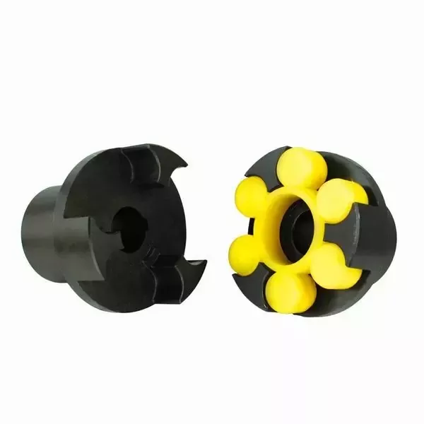
Product Overview
ZOOMRY Coupling Between motor and Reducer is an SL series snake spring coupling designed for reliable torque transmission in belt conveyor drive systems and industrial power trains. Combining the high torque capacity of a gear coupling with the flexible damping of an elastic coupling, it absorbs shock loads, compensates for minor misalignment, and protects connected equipment from overload damage. Models SL101 to SL125 cover rated torque from 45 Nm to 800,000 Nm at speeds up to 4,500 r/min, making it the ideal choice for conveyor drive applications across mining, cement, and heavy industrial operations.
How a Snake Spring Coupling Works
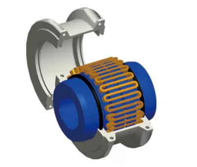
The SL series coupling uses a snake-shaped spring that fits into machined grooves on two serrated half-couplings — one connected to the motor shaft, the other to the reducer input shaft. When torque is applied, the spring compresses against the groove walls, transmitting power while absorbing vibration and impact loads. This design offers several advantages over rigid or gear-type couplings:
- Impact damping: The spring flexes under sudden load spikes, protecting the motor and reducer from shock damage — critical in crusher and conveyor start-up scenarios
- Misalignment tolerance: Accommodates angular, parallel, and axial misalignment without excessive wear
- Quick disassembly: The spring can be removed without moving the motor or reducer — reducing maintenance downtime
- No lubrication required: Unlike gear couplings, the spring-and-groove design operates dry, eliminating grease maintenance
How to Select the Right Coupling Model
Selecting the correct coupling size depends on three key parameters:
- Rated torque (Nm): The coupling's rated torque must exceed the motor's peak output torque. For conveyor drives, apply a service factor of 1.5–2.0 to account for start-up loads.
- Maximum speed (r/min): Ensure the coupling's allowable speed exceeds the motor's rated RPM. Higher-speed applications require smaller models within the same torque range.
- Shaft diameter (mm): The coupling must accommodate both the motor shaft (d1) and reducer input shaft (d2). Refer to the specifications table below for max shaft hole dimensions per model.
Quick reference: For a typical 90 kW conveyor drive motor (1,480 RPM, ~580 Nm rated torque), the SL105 (630 Nm rated) with a 1.5 service factor is the recommended starting point. For larger drives in long distance belt conveyors, SL110–SL115 models provide the necessary torque capacity.
Key Advantages
- Simple structure – easy to install and maintain with no special tools required
- Quick disassembly – spring removal without moving motor or reducer, cutting replacement downtime by 60%
- Long working life – precision-machined serrations and high-fatigue spring steel for 50,000+ hour service life
- Strong impact resistance – effectively protects motor and reducer from crusher and conveyor start-up shock loads
- Maintenance-free operation – no lubrication required unlike gear couplings, reducing ongoing maintenance costs
Specifications Table
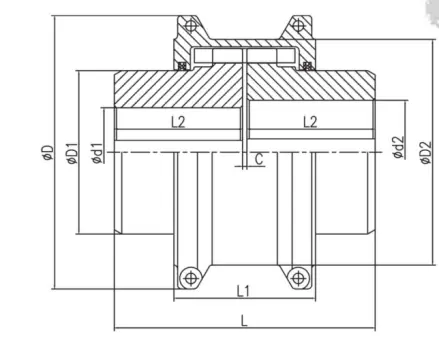
| Model | Rated Torque (Nm) | Allowable Speed (r/min) | Max Shaft Hole d1, d2 (mm) | D1 (mm) | D2 (mm) | L (mm) |
|---|---|---|---|---|---|---|
| SL101 | 45 | 4,500 | 28 | 40 | 80 | 107 |
| SL102 | 140 | 4,500 | 35 | 50 | 90 | 107 |
| SL103 | 224 | 4,500 | 42 | 55 | 100 | 107 |
| SL104 | 400 | 4,500 | 50 | 65 | 114 | 127 |
| SL105 | 630 | 4,350 | 56 | 75 | 130 | 127 |
| SL106 | 900 | 4,125 | 65 | 90 | 146 | 167 |
| SL107 | 1,800 | 3,600 | 65 | 105 | 168 | 228 |
| SL108 | 3,150 | 3,600 | 95 | 125 | 186 | 228 |
| SL109 | 5,600 | 2,440 | 110 | 140 | 214 | 290 |
| SL110 | 8,000 | 2,250 | 120 | 160 | 236 | 290 |
| SL111 | 12,500 | 2,025 | 140 | 180 | 260 | 290 |
| SL112 | 18,000 | 1,800 | 170 | 220 | 304 | 350 |
| SL113 | 25,000 | 1,650 | 180 | 255 | 336 | 350 |
| SL114 | 35,500 | 1,500 | 200 | 270 | 395 | 430 |
| SL115 | 50,000 | 1,350 | 240 | 305 | 435 | 430 |
| SL116 | 63,000 | 1,225 | 280 | 360 | 488 | 510 |
| SL117 | 90,000 | 1,100 | 300 | 395 | 530 | 510 |
| SL118 | 125,000 | 1,050 | 320 | 440 | 605 | 610 |
| SL119 | 180,000 | 900 | 360 | 500 | 660 | 610 |
| SL120 | 224,000 | 820 | 350 | 535 | 755 | 614 |
| SL121 | 315,000 | 730 | 420 | 570 | 825 | 670 |
| SL122 | 400,000 | 680 | 450 | 610 | 910 | 670 |
| SL123 | 500,000 | 630 | 480 | 650 | – | 773 |
| SL124 | 630,000 | 580 | 460 | 710 | – | 773 |
| SL125 | 800,000 | 540 | 500 | 760 | – | 913 |
※ Custom couplings available upon request. Contact ZOOMRY for detailed technical data or a quotation.
Related Equipment
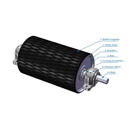
Ceramic lagged drive pulley for belt conveyor head-end power transmission.
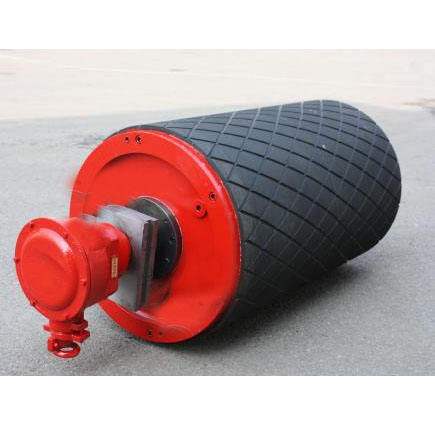
Integrated motor-gearbox drum — eliminates external coupling and saves drive space.
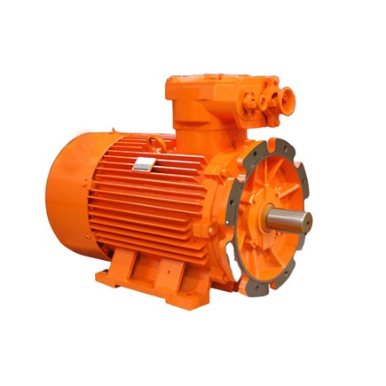
Integrated drive systems — motor, coupling, reducer, and backstop for belt conveyors.
Request a Quote for Motor-Reducer Coupling
Tell us your motor power, speed, and shaft diameters. Our engineers will recommend the optimal SL series coupling model for your drive system.
Get a Quote →