 ZOOMRY

1. Product Overview
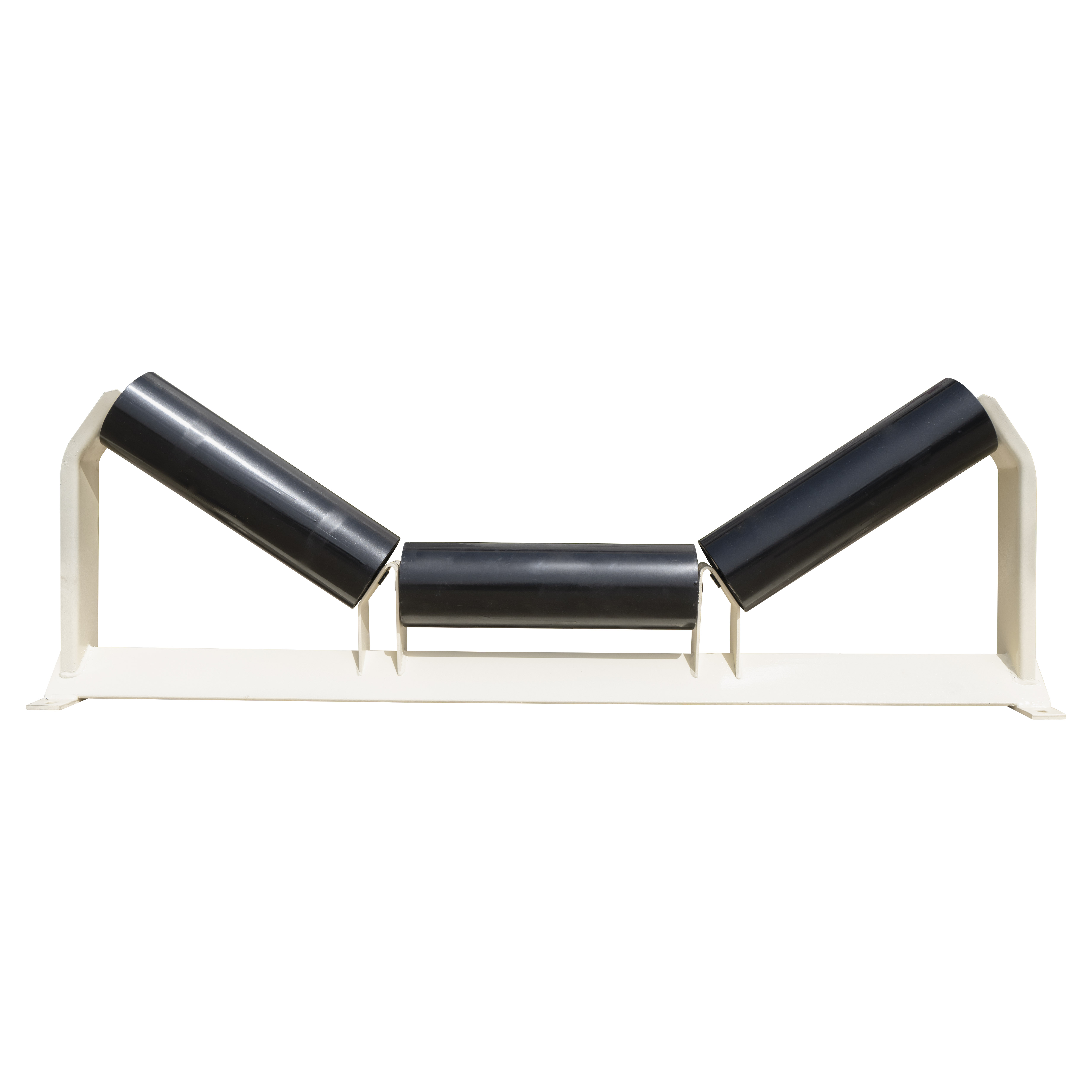
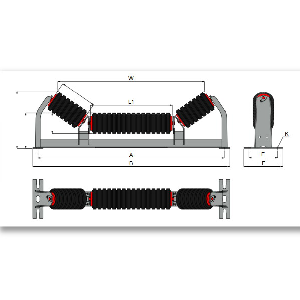
ZOOMRY CEMA C unequal impact troughing idlers combine offset roller geometry (L1 long center + L2 short wings) with rubber cushion rings for medium-duty loading zone protection. Engineered to CEMA C standards for mining and aggregate conveyors up to 42-inch belt width, these impact idlers absorb up to 80% impact energy at crusher discharge and transfer points. Available in 20° and 35° trough angles with 4-inch and 5-inch impact-rated rollers.
Unlike equal impact designs, the unequal roller configuration places a longer center roller where impact force is highest — improving belt tracking through loading zones. Rubber cushion rings on all three rollers compress under falling material, protecting the belt carcass in cement and aggregate crusher discharge applications.
2. How Unequal Impact Geometry Works
At conveyor loading zones, the center of the belt carries the heaviest material burden and receives the highest impact force. A standard equal-length roller design distributes support uniformly — but in high-impact applications, the center roller takes disproportionate stress.
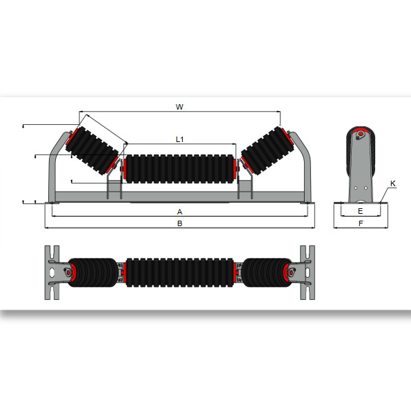
The CEMA C unequal impact troughing idler addresses this with an offset L1/L2 configuration: the center roller (L1) is longer, placing more rubber cushion rings directly under the impact zone, while shorter wing rollers (L2) provide stable edge support. This geometry improves belt tracking by up to 30% compared to equal impact designs at transfer points — critical in coal and mineral processing where off-center loading is common.
3. Key Features
Offset L1/L2 Roller Geometry — Longer center roller (L1) places more cushion rings under the primary impact zone, while shorter wing rollers (L2) provide stable edge support — improving belt tracking by up to 30% over equal impact designs.
Rubber Cushion Rings — Molded rubber rings on all three rollers absorb up to 80% impact energy, protecting the Conveyor Belt from puncture and carcass fatigue at transfer points.
CEMA C Medium-Duty Rating — 4-inch and 5-inch impact-rated rollers for belt widths up to 42 inches — ideal for medium-duty crusher discharge in mining and quarry operations.
Two Trough Angles — Available in 20° and 35° to match standard CEMA C carrying idler geometry, ensuring smooth belt transition into loading zones.
Advanced Labyrinth Sealing — Multi-stage seals protect bearings from fine dust and moisture, delivering 50,000+ hour service life in aggregate crushing environments.
4. Unequal Impact vs Equal Impact Troughing
| Feature | CEMA C Unequal Impact (C2) | CEMA C Equal Impact (C11) |
|---|---|---|
| Roller Configuration | L1 (long center) + L2 (short wings) | 3 equal-length rollers |
| Impact Distribution | Concentrated at center — more rings under L1 | Uniform across full belt width |
| Belt Tracking | Up to 30% improvement over equal impact | Standard — no enhanced tracking |
| Trough Angles | 20° and 35° | 20°, 35°, and 45° |
| Best For | Off-center loading, crusher discharge | Centered loading, transfer chutes |
5. Dimensions – CEMA C Unequal Impact Troughing 20° / 35°
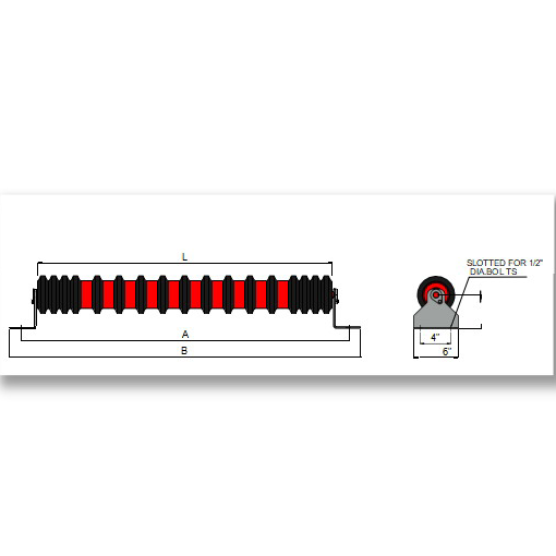
ZOOMRY CEMA C unequal impact troughing idlers are manufactured with 4-inch and 5-inch impact-rated roller configurations for belt widths from 18 to 42 inches at 20° and 35° trough angles:
|
|
4" Roller | 5" Roller |
|
|||||||||||
|---|---|---|---|---|---|---|---|---|---|---|---|---|---|---|
| Angle | BW | A | B | L1 | L2 | H1 | H2 | W | H1 | H2 | W | E | F | K |
| 20° | 18 | 27 | 29 | 11 1/2 | 4 1/2 | 6 1/2 | 8 5/8 | 21 1/4 | 7 | 9 1/16 | 20 7/8 | 6 | 8 | 1/2 |
| 24 | 33 | 35 | 15 7/16 | 5 7/16 | 6 1/2 | 8 5/8 | 27 1/4 | 7 | 9 1/16 | 26 15/16 | 6 | 8 | 1/2 | |
| 30 | 39 | 41 | 21 3/8 | 5 7/16 | 6 1/2 | 8 5/8 | 33 1/8 | 7 | 9 1/16 | 32 7/8 | 6 | 8 | 1/2 | |
| 36 | 45 | 47 | 27 3/8 | 5 7/16 | 6 1/2 | 8 5/8 | 39 1/8 | 7 | 9 1/16 | 38 7/8 | 6 | 8 | 1/2 | |
| 42 | 51 | 53 | 33 3/8 | 5 7/16 | 7 | 9 1/16 | 45 1/8 | 7 1/2 | 9 9/16 | 44 7/8 | 7 1/2 | 9 1/2 | 5/8 | |
| 35° | 18 | 27 | 29 | 10 7/16 | 5 3/8 | 6 1/2 | 10 3/16 | 19 1/8 | 7 | 10 9/16 | 18 11/16 | 6 | 8 | 1/2 |
| 24 | 33 | 35 | 13 1/4 | 6 3/4 | 6 1/2 | 10 3/16 | 24 7/8 | 7 | 10 9/16 | 24 7/16 | 6 | 8 | 1/2 | |
| 30 | 39 | 41 | 15 7/16 | 8 15/16 | 6 1/2 | 11 1/2 | 30 3/4 | 7 | 11 7/8 | 30 3/16 | 6 | 8 | 1/2 | |
| 36 | 45 | 47 | 21 3/8 | 8 15/16 | 6 1/2 | 11 1/2 | 36 5/8 | 7 | 11 7/8 | 36 1/16 | 6 | 8 | 1/2 | |
| 42 | 51 | 53 | 21 3/8 | 11 1/8 | 7 | 13 1/4 | 39 11/16 | 7 1/2 | 13 5/8 | 39 3/16 | 7 1/2 | 9 1/2 | 5/8 | |
Dimensions per CEMA C industry standards. A=Frame width, B=Overall width, L1=Center roller length, L2=Wing roller length, H1=Base height, H2=Overall height, W=Center-to-center mounting width, E/F/K=Mounting dimensions. All dimensions in inches.
Related Solutions

Need Impact Idlers for Your Crusher Discharge Zone?
Tell us your material type, lump size, and drop height — our engineers will recommend the optimal unequal or equal impact configuration.
Impact Idler Selection Guide →